

Thank you for choosing Rough Country for all your vehicle needs.
Rough Country recommends a certified technician install this system. In addition to these instructions, professional knowledge of disassemble/reassembly procedures as well as post installation checks must be known. Attempts to install this system without this knowledge and expertise may jeopardize the integrity and/or operating safety of the vehicle.
Please read instructions before beginning installation. Check the kit hardware against the parts list. Be sure you have all needed parts and know where they go. Also please review tools needed list and make sure you have needed tools.
If question exist, please call us @1-800-222-7023. We will be happy to answer any questions concerning this product. Check all fasteners for proper torque. Check to ensure for adequate clearance between all components.
Periodically check all hardware for tightness.
PRODUCT USE INFORMATION
WARNING The taller a vehicle is, the easier it will roll. We strongly recommend, because of rollover possibility that seat belts and shoulder harnesses should be worn at all times. Avoid situations where a side rollover may occur.
WARNING Generally, braking performance and capability are decreased when larger/heavier tires and wheels are used. Take this into consideration while driving. Do not add, alter, or fabricate any factory or after-market parts to increase vehicle height over the intended height of the Rough Country product purchased. Mixing component brands is not recommended.
Rough Country makes no claims regarding lifting devices and excludes any and all implied claims. We will not be responsible for any product that is altered. If questions exist we will be happy to answer them concerning the design, function, and correct use of our products.
The suspension system was developed using a 245-70/17 tire with 17 x 8 wheel with +38mm Offset. The lifts were designed to lift the front to level the vehicle. Due to manufacturing, dimension variances, and inflation all tire and wheel combinations should be tested prior to installation on all oversized / wider then stock tires.
DEALER AND VEHICLE OWNER
Any vehicle equipped with any Rough Country product should have a “Warning to Driver” decal installed on the inside of the windshield or on the vehicle’s dash. The decal should act as a constant reminder for whoever is operating the vehicle of its unique handling characteristics.
TORQUE SPECIFICATIONS

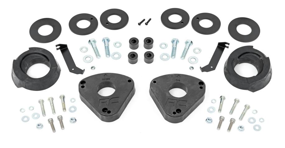
KIT CONTENTS
(2) Front Strut Spacer
(2) Front Strut Preloads
(1) Dr Side ABS Bracket
(1) Pass Side ABS Bracket
(2) Rear Coil Spacer Upper
(2) Rear Coil Spacer Lower
(4) Rear Trailing Arm Drop Spacer
HARDWARE INCLUDED
(4) 8MMx30MM Socket Head Bolts
(2) 8MMx50MM Hex Bolts
(4) 8MMx45MM Hex Bolts
(2) 5/16” Flat Washers
(2) 5/16” Lock Washers
(2) 10-24×3/8 Flanged Push Nut
(4) 14MM-2.0x60MM Hex Bolts
(4) 9/16 Flat Washers
(4) 9/16 Lock Washers
(2) 6mm x 30mm Button Bolt
TOOLS NEEDED
8MM Socket/Wrench
10MM Socket/Wrench
13MM Socket/Wrench
15MM Socket/Wrench
18MM Socket/Wrench
21MM Socket/Wrench
3/8” Socket/Wrench
Trim remover tool
Sander/Grinder
INSTALLATION INSTRUCTIONS
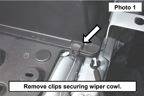
1. Lift the hood and remove the clips securing the wiper cowl. See Photo 1.
2. Lift up the cowl and remove the bolts for the upper strut cover using a 10mm wrench. See Photo 2.

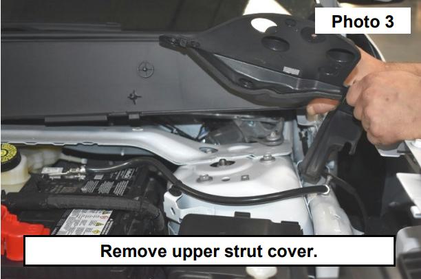
3. Remove upper strut cover. See Photo 3.
4. Jack up the vehicle and set on jack stands. Remove the wheels.
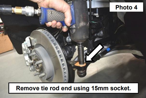
5. Remove the tie rod end using a 15mm socket/wrench. See Photo 4.
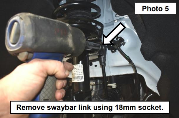
6. Remove the swaybar link using a 18mm socket/wrench. See Photo 5.
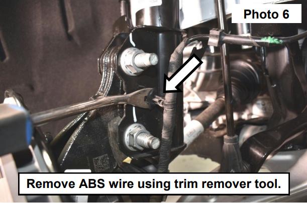
7. Remove ABS wire push pin from the knuckle using a trim remover tool. See Photo 6.
8. Slide the ABS wire off the bracket from the frame. See Photo 7.

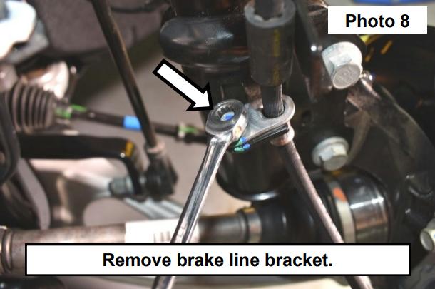
9. Remove the brake line bracket using a 8mm wrench. See Photo 8.
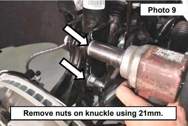
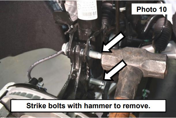
10. Remove the nuts on the knuckle using a 21mm socket/wrench. See Photo 9.
11. Strike bolts with a hammer to remove. See Photo 10.
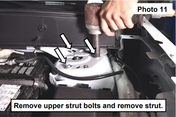
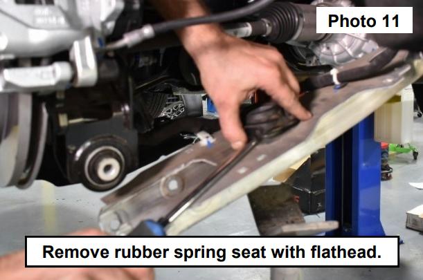
12. Remove upper strut bolts using a 13mm socket and remove strut from vehicle. See Photo 11.
13. Clamp the strut into a spring compressor and remove upper strut hat using a 18mm socket. See Photo 12.

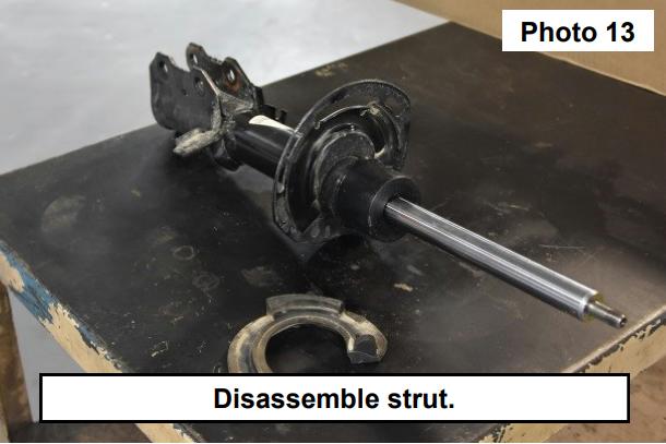
14. Disassemble the strut hat. Remove the shock boot and rubber isolator. See Photo 13.
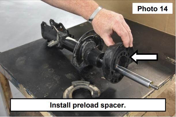
15. Install the supplied preload spacer to the strut and make sure it’s fully seated. See Photo 14.
16. Reinstall the rubber isolator and reassemble the strut. See Photo 15.

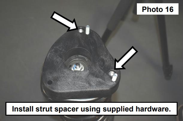
17. Install the front strut spacer with the supplied 8mm x 45mm hex bolts pointing up through the spacer and the 8mm x 30mm socket head bolts securing the spacer to the strut. Tighten using a 6mm Allen wrench. See Photo 16.
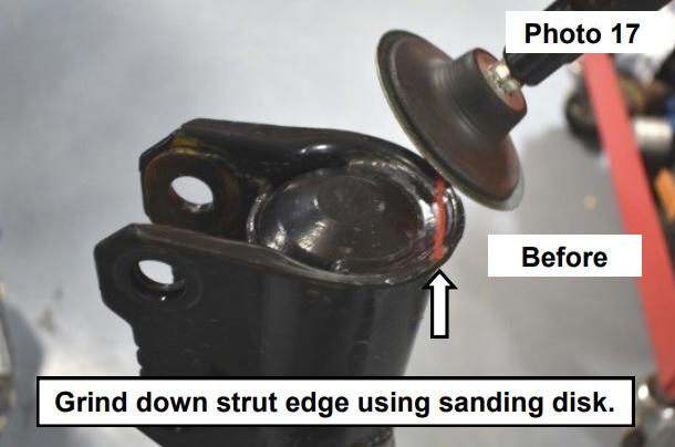
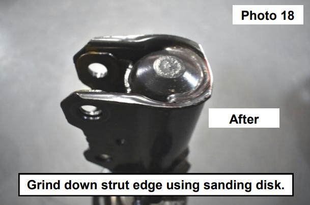
18. Grind down the edge of the lower strut using a sanding disk. See Photo 17 and Photo 18.
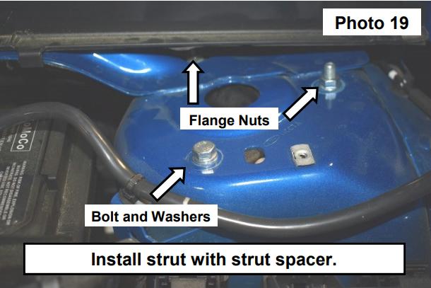
19. Install the strut with spacer back into the vehicle using the supplied 8mm flange nuts and 8MM x 50MM bolt, flat washer and lock washer in the 3rd hole. Tighten using a 13mm socket. See Photo 19.
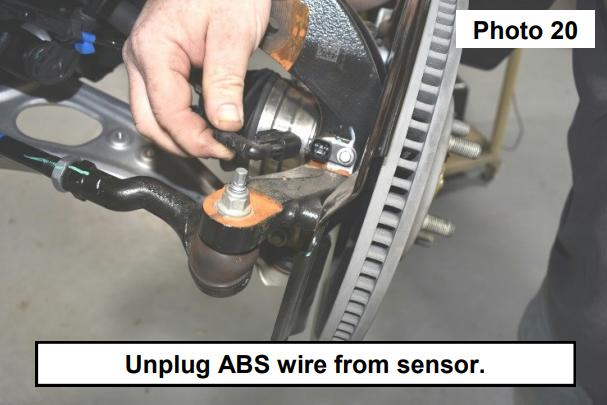
20. Unplug ABS wire from sensor. See Photo 20.
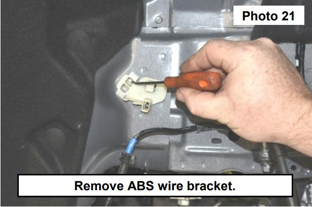
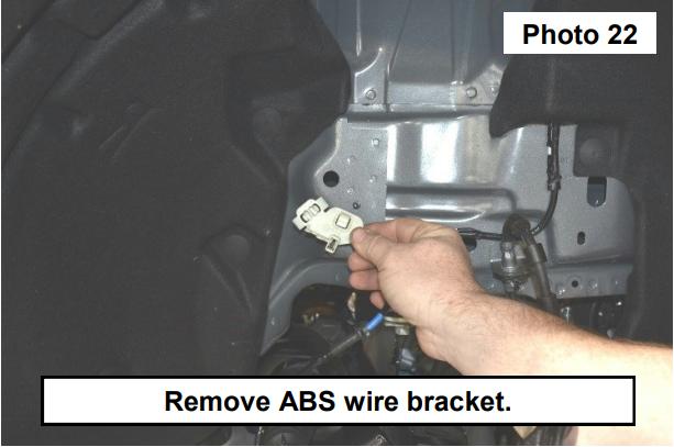
21. Remove the ABS bracket from the vehicle. See Photo 21 and Photo 22.
22. Reinstall the bolts for knuckle.
23. Reinstall tie-rod end.
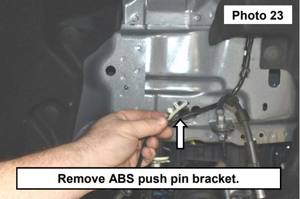
24. Remove the ABS push pin bracket using a trim remover tool and remove bracket from ABS line. See Photo 23.
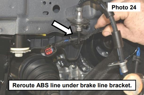
25. Reroute ABS line under the brake line bracket. See Photo 24.
26. Install the supplied ABS line bracket. See Photo 25.

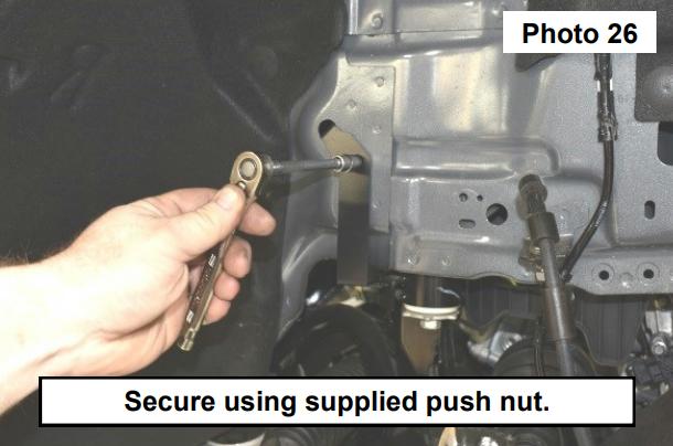
27. Secure the ABS bracket using the supplied push nut and 3/8” socket/wrench. See Photo 26.
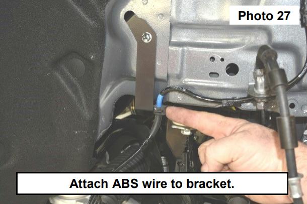
28. Attach the ABS wire to the bracket. See Photo 27.
29. Reinstall brake line bracket to the strut.
30. Reattach the ABS wire to the strut and the sensor.
31. Reinstall the upper strut cover and cowl.
32. Install wheels and lower.
REAR INSTALLATION INSTRUCTIONS
1. Jack up the rear of the vehicle and place on jack stands. Remove rear wheels.
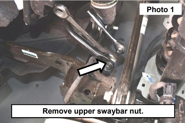
2. Remove the upper swaybar link nut using a 18MM wrench and T40 Torx bit. See Photo 1.
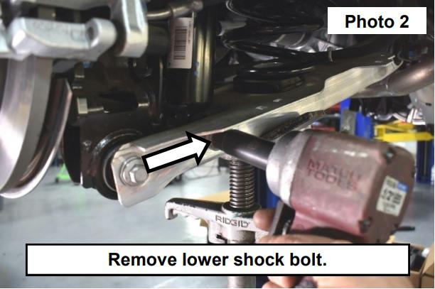
3. Remove the lower shock bolt using a 15mm socket/wrench. See Photo 2.
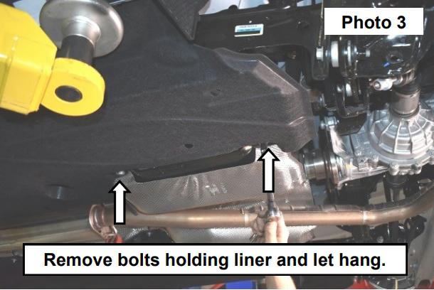
4. Remove two bolts holding the sound dampening liner and let it hang down to more easily access the trailing arm. See Photo 3.
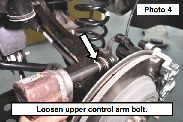
5. Loosen (NOT remove) the upper control arm bolt on the knuckle using a 15MM socket/wrench. See Photo 4.
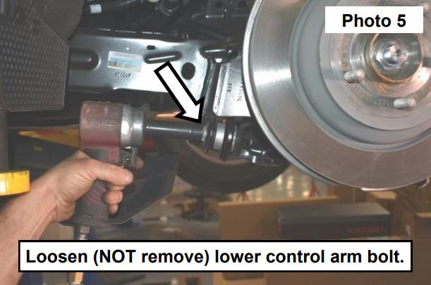
6. Loosen (NOT remove) the trailing arm bolt on the knuckle using a 15MM socket/wrench. See Photo 5.
7. Remove the lower control arm bolt on the knuckle using a 15MM socket/wrench. See Photo 6.

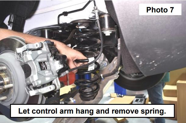
8. Let the lower control arm hang and remove the spring. See Photo 7.
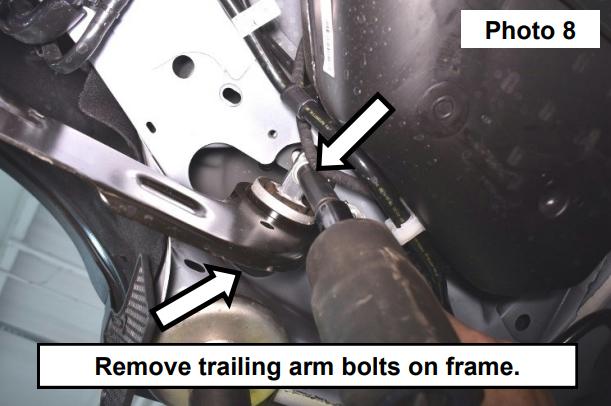
9. Remove the trailing arm bolts on the frame. See Photo 8.
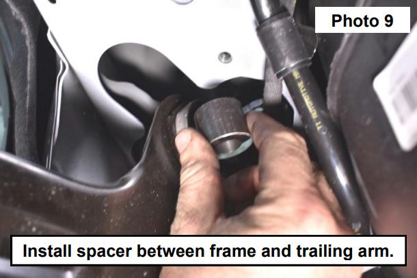
10. Install trailing arm Drop Spacer between the frame and trailing arm. See Photo 9.
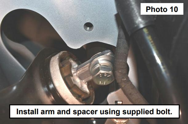
11. Install trailing arm with the Drop Spacer using the supplied 14MM-2.0x60MM bolts and 9/16” flat washers and lock washers. Tighten using a 21MM socket/wrench. See Photo 10.
12. Remove the rubber spring seat with a flathead screwdriver. See Photo 11 and Photo 12.

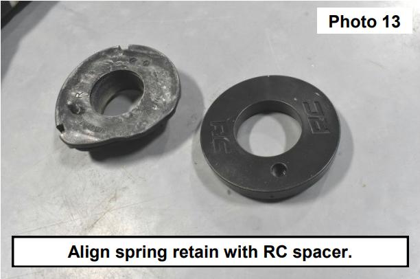
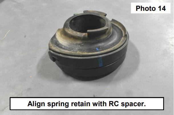
13. Align the spring retain with the supplied RC spacer. See Photo 13 and Photo 14.
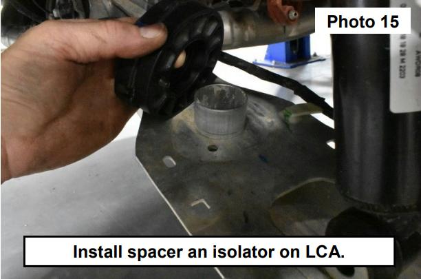
14. Install the spacer and isolator on the lower control arm. See Photo 15 and Photo 16.

15. Using a paint pen make a alignment mark from the body onto the coil spring isolator. Remove the isolator and install the thin upper spacer onto the body and reinstall the rubber coil spring isolator using the alignment mark. See Photos 17 and 18.


16. Install the spring on the Rear Coil Spacer and rubber spring seat. See Photo 19.

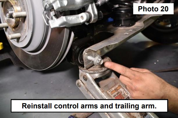
17. Reinstall the upper and lower control arms and trailing arm to the knuckle.
NOTE: You may need to use a jack to install the control arms. See Photo 20.
18. Reinstall the sound dampening liner.
19. Reinstall the shock.
20. Reinstall the swaybar link.
21. Apply steps for both sides of the vehicle.
22. Put on wheels and lower.